SPACE SHUTTLE
By Cliff Lethbridge
SPACE SHUTTLE PROGRAM HISTORY
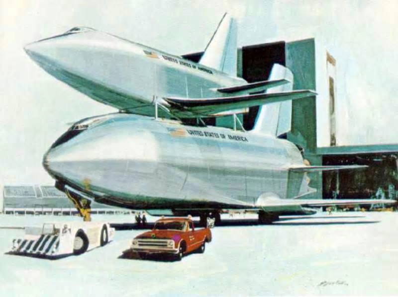
Space Shuttle Artist Conception, Photo Courtesy NASA
Born in 1968 at the height of the Apollo program, the Space Shuttle was designed to fulfill two basic roles in NASA post-Apollo manned flight objectives. The first goal of the Space Shuttle program was to provide NASA with an efficient, re-usable method of carrying astronauts to and from a permanently manned space station. At the time, NASA envisioned a space station which would be staffed by 12 to 24 people. The space station was intended to assure a permanent manned U.S. presence in space following the Apollo lunar landings. The space station would support a plethora of scientific research objectives, plus act as an engineering and support base for manned journeys to the planets. In addition, NASA believed that Space Shuttles could serve as multi-purpose satellite delivery vehicles with the potential to completely replace Atlas-Centaur, Delta and Titan rockets. The words “cheap” and “routine” were the words which most closely matched the objectives for Space Shuttles as expressed by NASA. Of course, history would prove otherwise.
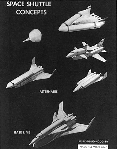
On January 31, 1969, NASA issued feasibility design study contracts for their “Integrated Launch and Re-entry Vehicle” (ILRV). Invitations were given to four aerospace contractors to present design proposals on re-usable and partially re-usable manned spacecraft. These companies presented reports to NASA by November 1, 1969. They unanimously recommended a fully re-usable, two-stage vehicle. Early in 1970, NASA refined their technical requirements for the vehicle. The name “Space Shuttle” first appeared in the “purpose” section of an official invitation for production contract bids issued on February 18, 1970. The name “Space Shuttle” subsequently became a permanent fixture for the vehicle, which NASA agreed should incorporate a fully re-usable, two-stage design.
Space Shuttle Concepts, Photo Courtesy NASA
With great optimism, NASA initially expected that the first Space Shuttle would enter service by 1977. In 1971, North American Rockwell and McDonnell Douglas were granted production contracts. From that point on, development of the Space Shuttle became extremely complicated, with the future of the vehicle often in doubt from one year to the next. At first, doubts surfaced about the feasibility of developing a two-stage Space Shuttle. To analyze these concerns, NASA issued study contracts to Grumman/Boeing, Lockheed and Chrysler in June, 1971. In basic terms, the initial NASA concept for the two-stage Space Shuttle called for a smaller manned winged vehicle to sit atop a larger manned winged vehicle. These would be pad-launched from a vertical position. The larger winged vehicle would be called the “Booster”, while the smaller winged vehicle would be called the “Orbiter”. The Booster would carry the Orbiter to an altitude of about 50 miles. The Orbiter would then separate and fire its own engines to reach orbit. After separation, the Booster would turn and descend through the atmosphere for a landing near the launch site. The Orbiter would return for a landing upon the conclusion of its space mission.
The Booster would, in essence, be a fuel tank with wings. In this two-stage concept, both the Booster and Orbiter would require cockpits, hardware and instrumentation to facilitate landings. Both were designed to carry internal turbo-fan engines which would produce controlled flight during landing operations. Each vehicle would carry its own fuel tanks. As originally described by NASA in 1970, this two-stage Space Shuttle would be able to carry a 25,000-pound payload to a maximum 300-mile circular orbit. As we now know, this early two-stage concept obviously does not resemble the Space Shuttles which were eventually built. This was due to the economic realities facing NASA in the early 1970’s. In a time of general recession, it was clear that NASA could not afford to build a fleet of complicated two-stage Space Shuttles along with a space station at the same time. Utilizing the intent of the day for the Space Shuttle, one without the other made no sense at all.
Space Shuttle Concepts, Photo Courtesy NASA
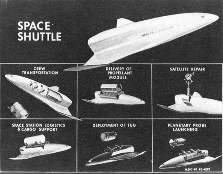
Matters were further complicated in 1971 as NASA negotiated with the U.S. Air Force regarding shared use of the Space Shuttle fleet. Military funding for the Space Shuttle program was vital if NASA hoped to build the vehicle at all. But the U.S. Air Force specified a total payload capability of 65,000 pounds for Space Shuttles capable of carrying large, sophisticated military satellites into orbit. This figure was nearly three times more than NASA had originally planned. These major factors led to a dramatic redesign of the Space Shuttle and the proposed space station. The NASA space station was originally designed following the Skylab pattern. A single multi-deck structure which made up the space station would be carried into orbit by a Saturn V rocket. Space Shuttles would then only be needed to ferry astronauts, equipment and supplies. It was thought that this type of space station would have a useful life of about ten years, at which time it could simply be replaced by another. However, an “all at once” space station did not fit the NASA budget.
NASA decided to adopt a modular concept for the space station. The space station would be built piece by piece over a period of years, with separate modules carried into orbit by Space Shuttles. This was a prudent move for NASA. Not only did it provide a more realistic approach for constructing a space station, it also made possible the production of a redesigned Space Shuttle capable of carrying heavy military payloads and even commercial satellites. In redesigning the Space Shuttle as a space station module carrier, U.S. Air Force payload criteria were met, thus assuring critical military funding. Just as important, the redesign would allow NASA to carry a plethora of satellites aboard Space Shuttles. Over time, this could produce tremendous cost savings for NASA. Not only could NASA secure private funding to carry commercial satellites aboard Space Shuttles, the costs of maintaining Atlas-Centaur, Delta and Titan rocket fleets could be phased out and ultimately eliminated.
Space Shuttle Artist Conceptions, Photo Courtesy NASA
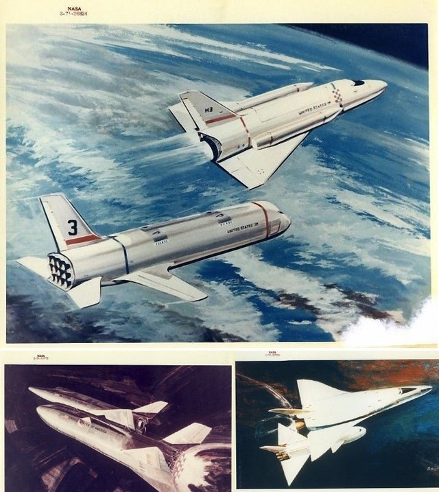
With an event like the Challenger explosion never anticipated, NASA made a decision, so to speak, to “put all of their eggs in one basket”. The Space Shuttle was to be a multi-purpose manned vehicle which would carry NASA into the next century. Even with major design modifications, NASA faced a huge price tag for its Space Shuttle fleet. On July 1, 1971, NASA granted four-month contract extensions to Rockwell and McDonnell Douglas to come up with methods of cutting their projected $10 billion development costs. The contractors decided that the most suitable method of cutting costs was to scrap the manned Booster stage of the Space Shuttle. NASA opted instead to create a more traditional expendable system to carry the manned Orbiter into space. NASA kept the manned Booster on the drawing boards, though, in case it could be afforded at a later date. Reduction in the overall size and complexity of the Space Shuttle booster system and redesign of the Orbiter did provide cost savings, but additional changes were ahead.
A smaller version of the Orbiter, called Mark I, was planned initially. This could later be replaced by a larger Mark II version of the Orbiter. The development of the Mark I and Mark II Space Shuttle fleet was to be phased in over a period of several years. The Orbiter itself could be scaled down considerably as NASA agreed to use external fuel tanks to carry the fuel the spacecraft would need to reach orbit. In previous designs, the Orbiter would carry its own fuel tanks on board. In September, 1971, Boeing proposed using a modified S-IC first stage from the Saturn V to act as a main fuel tank for the Space Shuttle. In one version, the S-IC could be equipped with a crew compartment, wings and aerodynamic equipment to facilitate a manned Booster landing. The “Re-usable S-IC” Booster, called RS-IC, would carry the Orbiter aloft. Following separation, the Orbiter would reach orbit powered by its own engines, fed by two external liquid hydrogen tanks which would be jettisoned in space. The RS-IC would then return for a landing.
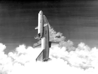
Space Shuttle Artist Conception, Photo Courtesy NASA
A more cost-effective version involved using a modified S-IC Saturn V first stage as an unmanned Booster which would be attached to a large external fuel tank. This array would be mated to the Orbiter. The S-IC would then act as an expendable Booster which would separate at an altitude of about 45 miles, leaving the Orbiter to reach orbit using its own engines fueled by the remaining single external fuel tank which would be jettisoned in space. With the exception of the S-IC booster, this design was somewhat similar to the vehicles which eventually flew. The S-IC option was scrapped because the booster burned liquid oxygen and kerosene. This fuel combination was deemed too inefficient for the Space Shuttle.
Space Shuttle development contracts for Rockwell, Grumman/Boeing and Lockheed were extended through February, 1972, and two core concepts for the spacecraft emerged. These were divided into parallel burn and series burn concepts. In the parallel burn concept, the Orbiter’s engines ignited at the same time as the Booster. The Orbiter’s engines would fire all the way to orbit, which would require them to be fed by a large external fuel tank. The Booster system would be jettisoned at some point during ascent. Initial options for the Booster called for various combinations of large or medium-sized solid rocket boosters with the possibility of high-pressure liquid fuel assist. One popular parallel burn Booster combination called for two large solid rocket boosters to be assisted by four smaller solid rocket boosters which would be strapped to the Orbiter’s large external fuel tank.
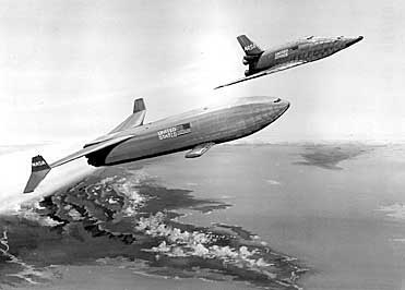
Space Shuttle Artist Conception, Photo Courtesy NASA
In the series burn concept, or multi-stage approach, the Orbiter’s engines would still be fed by an external fuel tank. However, the Orbiter’s engines would not fire until a first stage Booster had first been expended in flight. Series burn first stage arrays on the drawing board for the Space Shuttle called for various combinations of clustered solid rocket boosters, clustered modified Saturn V F-1 engines or new high-pressure liquid fueled engines. NASA again encountered development difficulties because all of the parallel and series burn concepts presented proved to be too expensive to be manufactured under tight budgetary constraints. A company named Mathematica was retained by NASA to perform an economic analysis of the entire Space Shuttle program. The company would recommend the most cost-effective design for the vehicle, as well as tally funding alternatives such as commercial launch revenue.
Mathematica did provide some encouragement at a critical time for NASA. It was almost immediately determined that the U.S. manned space program would be more cost-effectively served by Space Shuttles rather than continued use of expendable rockets like Saturn IB and Saturn V. The federal Office of Management and Budget (OMB) scrutinized NASA expenditures and the agency’s proposals for the Space Shuttle. Initial reactions of OMB to the Space Shuttle were not encouraging, so NASA took its case directly to President Richard M. Nixon. Late in 1971, there was a chance that the Space Shuttle program would be halted for more than one year. NASA had no guarantee that President Nixon would recommend any expenditures for the Space Shuttle in his fiscal year 1973 budget, which ran from July 1, 1972 to June 30, 1973. President Nixon was ready to present his fiscal year 1973 budget to the U.S. Congress in early January, 1972. If he did not endorse funds for the Space Shuttle in this budget, the program could have faced a stall until July, 1973 at the earliest.
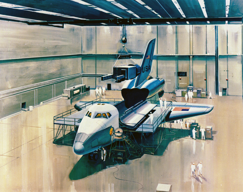
Space Shuttle Artist Conception, Photo Courtesy NASA
NASA Administrator James Fletcher and NASA Deputy Administrator George Low met with President Nixon for 45 minutes at the “San Clemente White House” on January 5, 1972. A decision had already been made based on previous correspondences between NASA and the President. At 11:15 a.m. Pacific Time on January 5, 1972, President Nixon announced his commitment to fund the development of the Space Shuttle. Just 19 days later, his budget was presented to Congress. Necessary funding for the Space Shuttle was ultimately approved. NASA still lacked a firm design for the Space Shuttle. Mathematica reported that two options remained economically feasible for the Booster stage. Either a large solid rocket booster system or a high-pressure liquid fueled Booster system were considered feasible.
A high-pressure liquid fueled series or parallel burn Booster was projected to cost $7 billion to develop and $100 per pound of payload to operate. A parallel burn Booster utilizing large solid rocket boosters was projected to cost $5.5 billion to develop and $160 per pound of payload to operate. While the Booster employing large solid rocket boosters would likely be more expensive to operate, NASA opted to take advantage of huge cost savings up front. Since costs of ultimate operation could be absorbed throughout the life of the Space Shuttle program, the parallel burn Booster using large solid rocket boosters was selected. On March 15, 1972, NASA officially announced plans to incorporate this design into the Space Shuttle. The solid rocket boosters were to be recovered and re-used following each launch. NASA claimed each solid rocket booster could be flown 100 to 500 times prior to retirement. As per this parallel burn configuration, the Orbiter’s engines would be ignited at launch and fed by liquid fuel contained in a large external fuel tank which would be jettisoned after the spacecraft neared orbit.
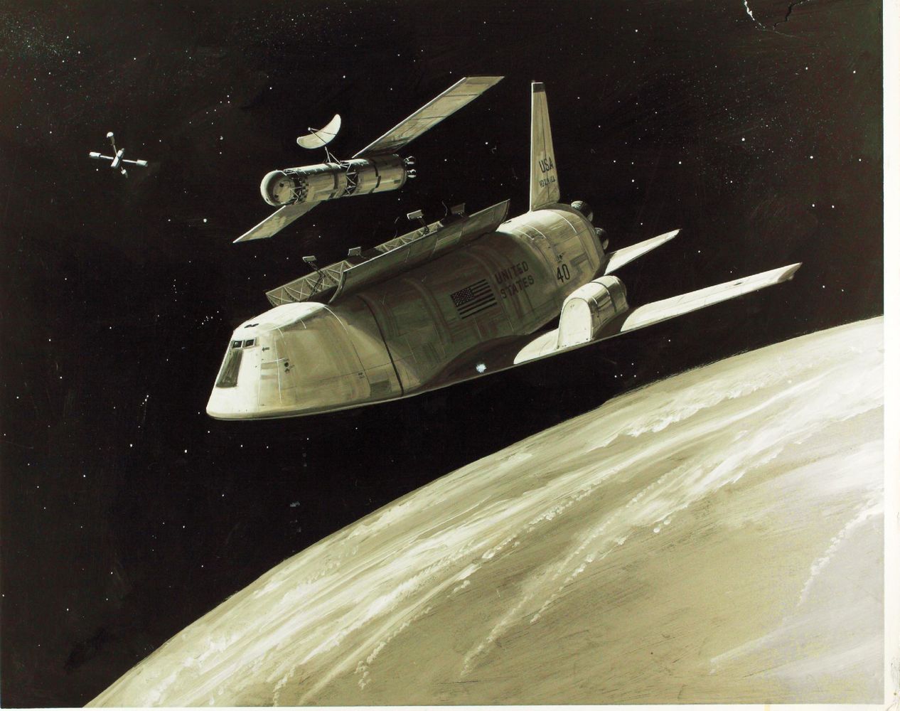
Space Shuttle Artist Conception, Photo Courtesy NASA
On March 17, 1972, NASA requested bids for construction of the Orbiter. Responses from Rockwell, Grumman, McDonnell Douglas and Lockheed were received by May 12, 1972. Space Shuttle Main Engine (SSME) development remained the responsibility of Rocketdyne under a contract which had already been issued in July, 1971. NASA updated their SSME specifications and submitted them to Rocketdyne in April, 1972. The International Space Division of Rockwell received the contract to develop and manufacture the Orbiter, as well as manage overall vehicle integration, on July 25, 1972. By this time, the accepted design of the Space Shuttle was quite similar to the vehicles that eventually entered service. However, a few design changes would follow. NASA made a decision to scrap two abort solid rocket motor assemblies which would have been attached to the Orbiter’s tail. During an in-flight emergency, these motors would have been fired to propel the Orbiter away from its main solid rocket boosters.
It was determined that the Space Shuttle’s main engines would be able to adequately guide the spacecraft away from the solid rocket boosters if a “Return-to-Launch Site” (RTLS) abort became necessary. In addition, two turbofan engines which would have been fitted to the Orbiter’s rear fuselage were scrapped. The turbofan engines would have enabled the Orbiter to maintain powered flight during landing operations and powered flight transfer between ground facilities. Instead, NASA decided that the Orbiter could safely glide to a landing. Point-to-point flying of the Orbiter between facilities would be accomplished by carrying the spacecraft “piggyback” atop a modified Boeing 747 aircraft. Martin Marietta was granted a construction contract for the Space Shuttle’s External Tank (ET) in August, 1973. Originally, this contract specified that a small solid rocket booster be attached atop the ET.
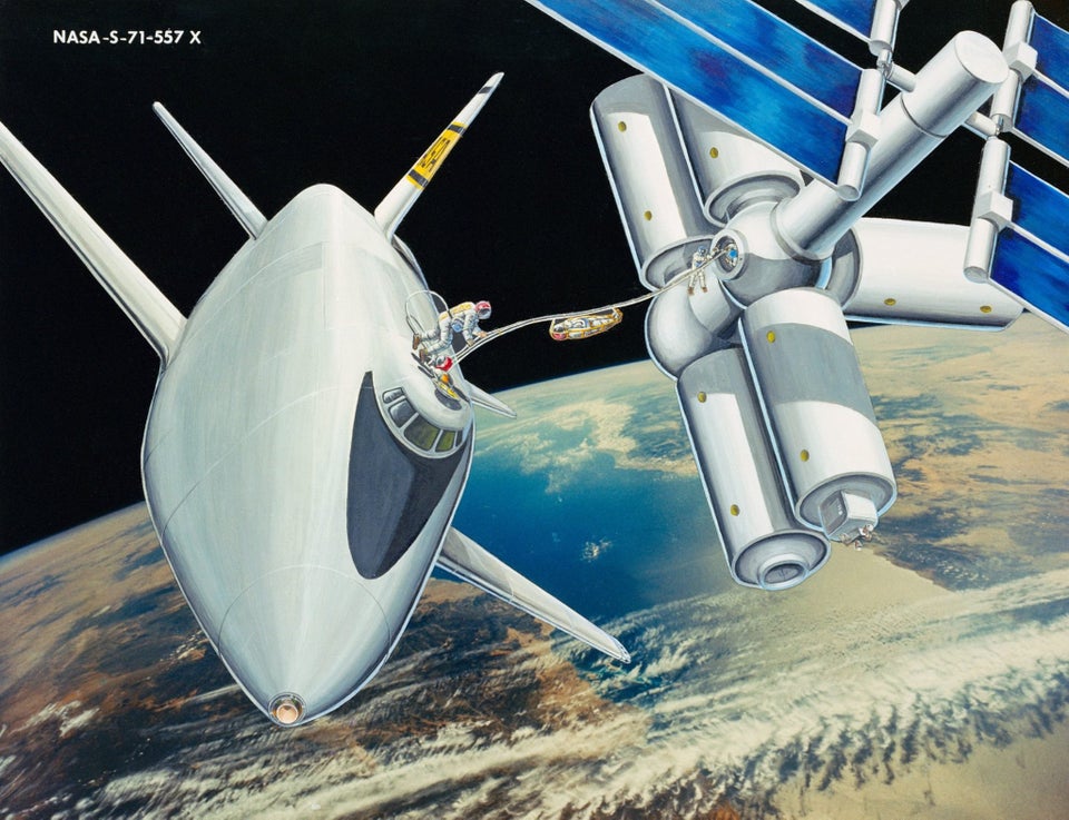
Space Shuttle Artist Conception, Photo Courtesy NASA
The small solid rocket booster would be fired following ET jettison to propel the tank back toward the atmosphere. However, studies indicated that the ET could not achieve orbit on its own inertia and would fall back, then break up in the atmosphere by itself. Thiokol Corporation was granted a contract to manufacture the Space Shuttle’s Solid Rocket Boosters (SRB) in November, 1973. The company had already demonstrated a successful track record of providing reliable solid rocket boosters for a plethora of rockets. A dispute regarding the SRB contract was initiated by Lockheed following its issuance. While the contract remained with Thiokol after a resolution of the action, the grievance process effectively froze the contract until June, 1974. Rockwell began work on Space Shuttle Enterprise, designated Orbiter Vehicle-101 (OV-101), on June 4, 1974. All of the subcontractors delivered their Enterprise components to Rockwell by the end of 1975.
Enterprise was rolled out of the Rockwell hangar at Palmdale, California on September 17, 1976. The spacecraft was subsequently rolled to the NASA Dryden Flight Research Center at Edwards Air Force Base, California for flight testing. Rockwell continued the development of Space Shuttles Columbia (OV-102), Discovery (OV-103) and Atlantis (OV-104). Although Enterprise was intended to be re-fitted as an operational Space Shuttle, NASA opted instead to construct Challenger (OV-099) from what was originally a high-fidelity Structural Test Article (STA-099). NASA anticipated that its full fleet of four Space Shuttles would be in complete operation by 1984. NASA would decide to build a fifth operational Space Shuttle, Endeavour (OV-105), specifically to replace Challenger, which was lost on January 28, 1986. However, a fifth operational Space Shuttle was not originally anticipated.
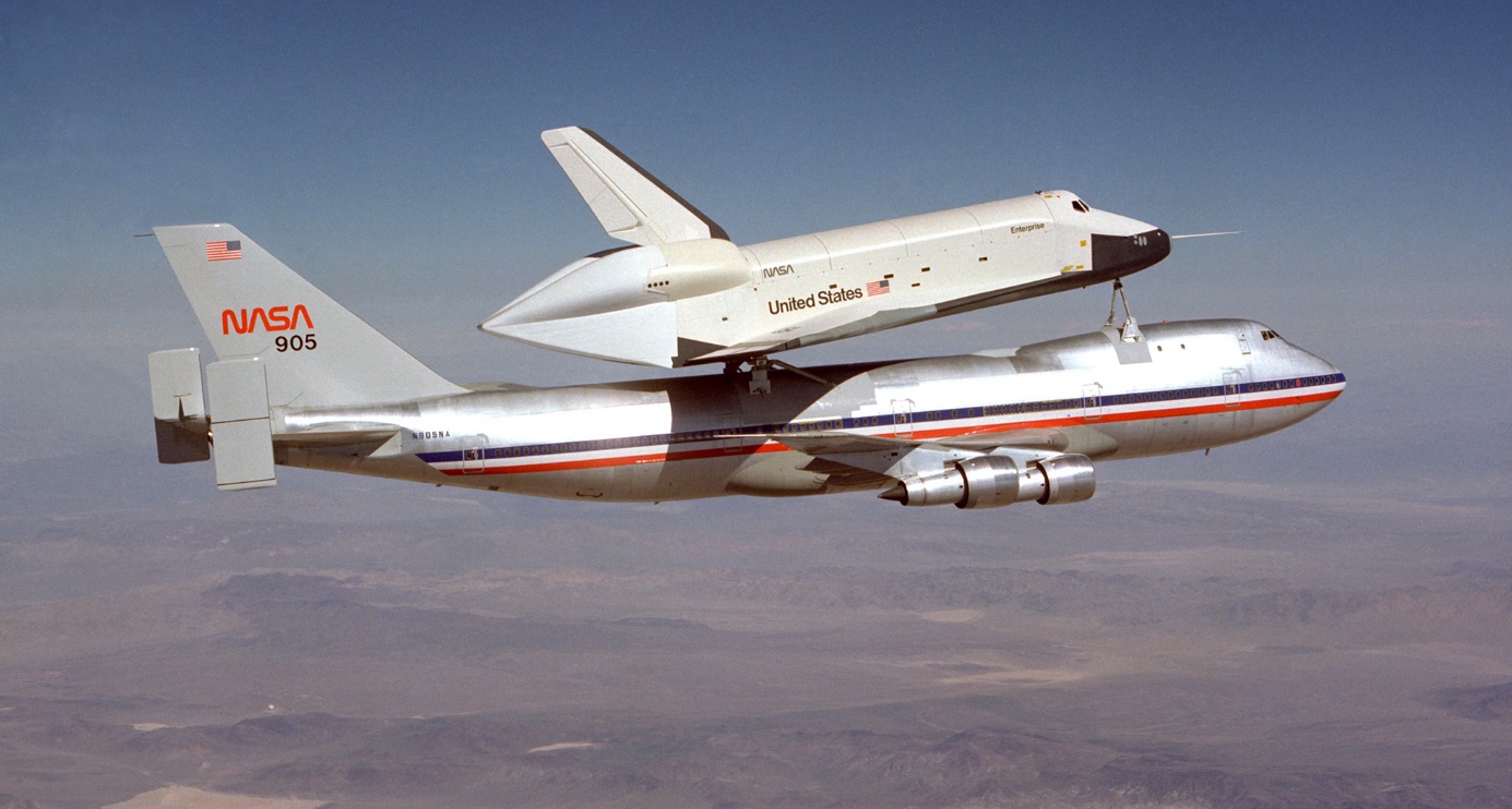
Space Shuttle Enterprise, Photo Courtesy NASA
NASA expected the Space Shuttle fleet to ultimately complete 25 to 60 missions per year. Plans called for up to 20 launches per year from each of three launch pads. Although NASA reviewed several detailed proposals for constructing virgin Space Shuttle processing, launch and landing sites in various parts of the country, the space agency wisely opted to conserve scarce resources by modifying existing facilities. The two Apollo launch pads at the Kennedy Space Center, 39A and 39B, were renovated for the Space Shuttle. A third Space Shuttle launch site was constructed at Vandenberg Air Force Base, California by renovating Titan III launch complex SLC-6, nicknamed “Slick-6”, although Space Shuttles never ended up being launched from there.
One of the first important tasks of the Space Shuttle fleet was to have been to boost the Skylab space station to a higher orbit. NASA had considered renovating and occupying Skylab as a cost-effective way of starting up a “new” space station program. When Skylab was initially abandoned on February 8, 1974 it was purposely boosted to a slightly higher orbit which varied from 269 to 283 miles. Calculations indicated that Skylab would remain in orbit for at least nine years, giving NASA ample time to get the Space Shuttle program rolling. NASA had optimistically envisioned that a Space Shuttle would be able to attempt a docking with Skylab as early as the fifth Space Shuttle flight, which was originally expected to occur as early as the latter part of 1979. The Skylab rescue mission was formally approved by NASA in September, 1977 and slated for the fifth Space Shuttle flight. In November, 1977 NASA awarded a contract to Martin Marietta for the design and construction of suitable docking and boost mechanisms.
By late 1978, National Oceanographic and Atmospheric Administration studies indicated that solar activity was forecast to become the second most intense in the century, with solar winds likely to be strong enough to increase atmospheric drag and cause Skylab to decay to much lower altitudes within a year. The revelation prompted NASA to determine how, if necessary, Skylab could be guided back to Earth in a manner necessary to avoid damage to populated areas. NASA was also prompted to step up its development of Space Shuttle hardware necessary to save the space station. Martin Marietta had already designed a teleoperator docking unit that could be remotely guided by an astronaut to dock with Skylab. Once docking was completed, engines in the docking mechanism could be fired to boost Skylab to a safe orbit. The docking unit was scheduled to be delivered to the Kennedy Space Center by August, 1979 for a Space Shuttle flight scheduled for September, 1979. Due to development delays, the September, 1979 Space Shuttle flight would be the third, not the fifth as envisioned. It was discovered that Skylab operational systems were working well, and NASA remained optimistic that the space station could be saved. But time was clearly running out. The effort to save Skylab ended abruptly in December, 1978.
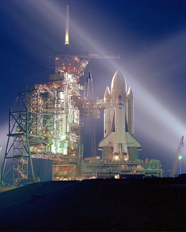
Space Shuttle Columbia, Photo Courtesy NASA
NASA had run into development problems with the Space Shuttle Main Engines, and it became clear that even the first Space Shuttle launch would not occur until well after the solar winds had increased atmospheric drag and forced the Skylab orbit to decay beyond hope of rescue. On December 15, 1978 NASA Administrator Robert Frosch informed President Jimmy Carter that Skylab could not be saved, and that NASA would attempt to guide the space station to a controlled re-entry as far away from populated areas as possible. Skylab, however, would refuse to die quietly. At 3:45 a.m. EDT on July 11, 1979 controllers at the NASA Johnson Space Center commanded Skylab to tumble, hoping the space station would break apart upon re-entry. It did not, however, break apart as expected, and at 12:37 p.m. EDT on July 11, 1979 Skylab rained debris near Perth, Australia. Although the Skylab rescue mission was never completed, the Space Shuttle fleet was slated to support the launch of a plethora of scientific, commercial and military satellites. It would also facilitate on-orbit scientific investigations and aid NASA in a slower, more methodical approach to completing a space station.
The Space Shuttle fleet was never, however, destined to perform up to 60 missions per year as intended. As NASA approached a more modest launch rate of about 24 missions per year by the late 1980’s, the Space Shuttle had already proven to be much more expensive and time-consuming to service and maintain than originally envisioned. And, the entire program was halted on January 28, 1986 when Space Shuttle Challenger exploded 73 seconds after launch. This was just the 25th Space Shuttle mission, and it became stunningly clear that major modifications to the entire Space Shuttle program were called for. With the launch of Space Shuttle Discovery on September 29, 1988 NASA entered a brand new era of Space Shuttle operations, adopting a more relaxed pace averaging about eight launches per year. Learning from one of its greatest tragedies, NASA was able to rebuild and maintain a Space Shuttle program that has been remarkably safe and reliable, with the exception of the loss of Space Shuttle Columbia on February 1, 2003.
SPACE SHUTTLE CONSTRUCTION AND OPERATION
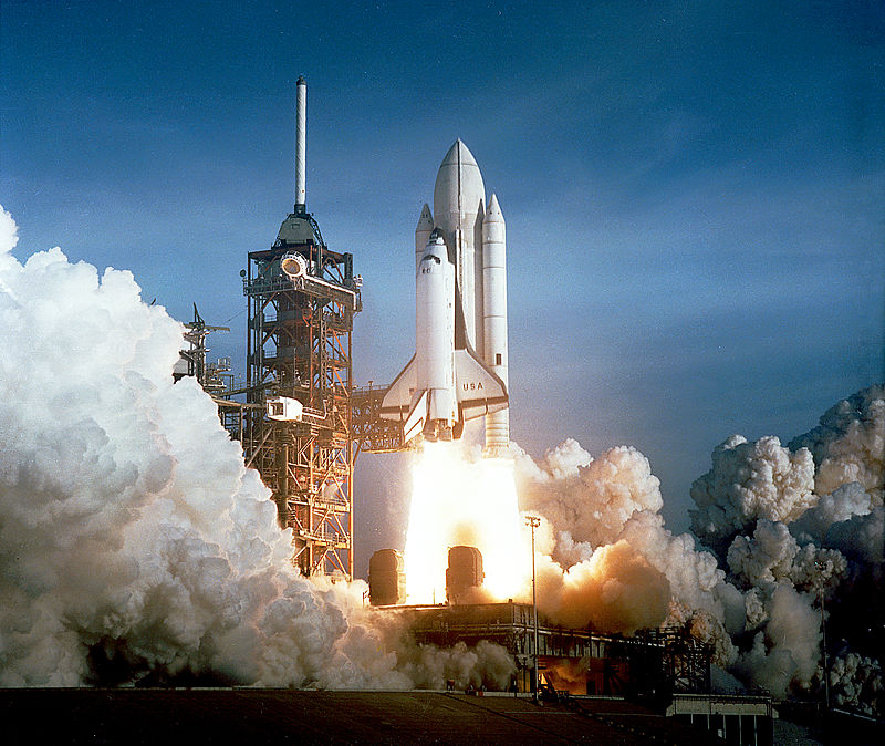
Space Shuttle Columbia, Photo Courtesy NASA
Space Shuttle Orbiter Length: 122 feet, 2 inches
Space Shuttle Orbiter Height: 56 feet, 8 inches
Space Shuttle Orbiter Diameter: 22 feet, 8 inches
Space Shuttle Orbiter Wingspan: 78 feet, 1 inch
Date of First Space Shuttle Launch: April 12, 1981
Date of Final Space Shuttle Launch: July 8, 2011
Number of Space Shuttle Launches: 135
The following information is more or less common to all Space Shuttles. Although the Space Shuttle program was retired in 2011, this information is included here for historic and research purposes.
The Space Shuttle Orbiter is constructed in major sections. These include:
1. The Forward Fuselage, which is made up of lower and upper sections that form a clamlike shell around a pressurized crew compartment. It houses the crew compartment and supports the forward reaction control system module, nose cap, nose gear wheel well, nose gear, nose gear doors and forward Orbiter/External Tank attachment.
2. The Crew Compartment, which is a pressurized three-level compartment intended to support all astronaut activities aboard the Orbiter. The Crew Compartment has a side hatch for normal crew ingress and egress which can be blown in an emergency.
The Crew Compartment also contains a hatch into an airlock from the middeck, and a hatch from the airlock through the aft bulkhead into the payload bay to support either spacewalks or access to pressurized modules in the payload bay area.
The Crew Compartment has 11 windows, including six forward windows, two overhead rendezvous observation windows, two aft payload bay viewing windows and a single side hatch window. Three panes make up each window. At a total width of nearly three inches, these are the thickest windows ever designed for see-through flight applications.
The Crew Compartment contains three levels, including a flight deck located at the top, a middeck in the center and a lower level equipment bay. The Crew Compartment is pressurized at 14.7 pounds per square-inch with an atmosphere of 80% nitrogen and 20% oxygen. This accommodates the crew with a shirt-sleeve working environment.
3. The Airlock, which is typically housed in the crew compartment middeck. The Airlock is 83 inches long and has a diameter of 63 inches. Two pressurized sealing hatches and a complement of support system hardware are contained in the Airlock. Each sealing hatch has a four-inch diameter observation window.
Depending on the mission application, the Airlock can be positioned in either the crew compartment or the payload bay in support of spacewalk activities. The Airlock can also be modified to employ a tunnel adapter hatch, tunnel adapter and tunnel to allow the crew to enter pressurized modules in the payload bay.
4. The Wings, which provide an aerodynamic lifting surface to produce conventional lift and control for the Orbiter. The left and right Wings consist of the wing glove and an intermediate section that includes the main landing gear wells.
The Wings also include a torque box, a forward spar for mounting the reusable leading edge structure thermal protection system, the wing/elevon interface, the elevon seal panels and the elevons, which provide flight control during atmospheric flight. Each Wing is 60 feet long and has a maximum thickness of 5 feet.
5. The Midfuselage, which provides a structural interface for the forward fuselage, aft fuselage and wings. It supports the payload bay doors, hinges, tie-down fittings, forward wing glove as well as various Orbiter system components. The Midfuselage provides the structural foundation for the payload bay.
6. The Payload Bay Doors, which are opened shortly after orbit is achieved to allow heat to be released from the Orbiter and to allow the release of payloads as necessary. The two Payload Bay Doors are hinged at the port or starboard side of the midfuselage and are latched at the centerline atop the Orbiter.
Thermal seals on the Payload Bay Doors provide a relatively airtight environment within the payload bay when the doors are closed. This seal is critical when ground operations require equipment and payloads to be maintained within the payload bay. Each Payload Bay Door is 60 feet long by 15 feet wide.
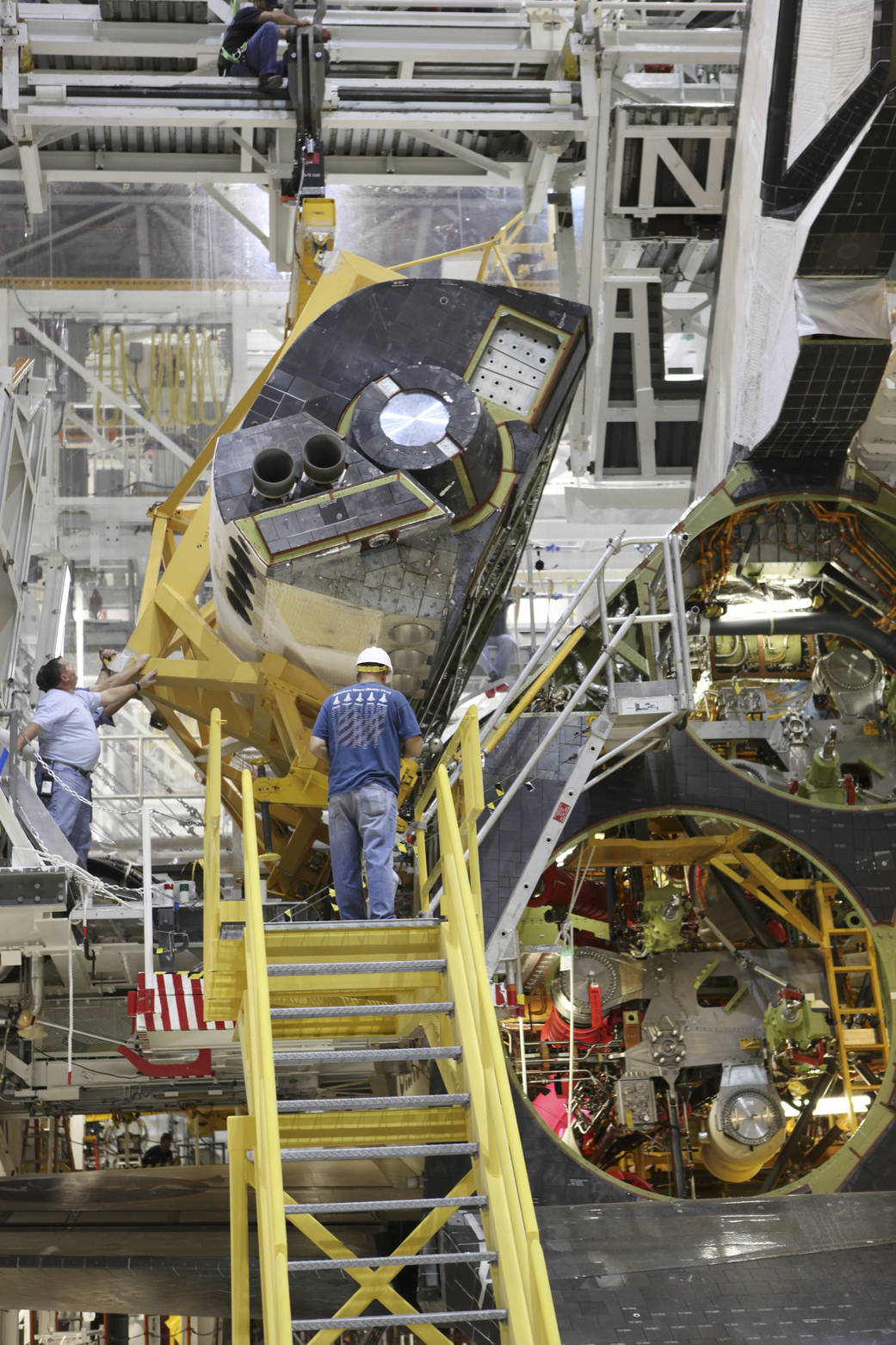
Space Shuttle Orbital Maneuvering System Pod, Photo Courtesy NASA
7. The Aft Fuselage, which consists of an outer shell, thrust structure and internal secondary structure. The Aft Fuselage supports and interfaces with the left-hand and right-hand aft orbital maneuvering system/reaction control system pods.
The Aft Fuselage also supports and interfaces with the wing aft spars, midfuselage, Orbiter/External Tank rear attachments, Space Shuttle Main Engines, aft heat shield, body flap, vertical tail and two pre-launch umbilical panels.
The Aft Fuselage outer shell allows access to systems installed within the structure. The Aft Fuselage thrust structure supports the three Space Shuttle Main Engines and their hardware. The Aft Fuselage internal secondary structure houses hardware and wiring for auxiliary power unit, hydraulics, ammonia boiler and flash evaporator systems.
8. The Orbital Maneuvering System/Reaction Control System Pods, which are attached to the upper aft fuselage left and right sides and contain all of the Orbital Maneuvering System (OMS) and Reaction Control System (RCS) propulsion elements that are located at the aft of the Orbiter.
9. The Body Flap, which provides a thermal shield for the three Space Shuttle Main Engines during re-entry and provides the Orbiter with pitch control trim during atmospheric flight.
10. The Vertical Tail, which consists of a structural fin surface, a rudder/speed brake surface, a tip and a lower trailing edge. The Vertical Tail provides aerodynamic stability for the Orbiter during flight, and its rudder can be split into two halves to act as a speed brake during landing.
The Space Shuttle Orbiter remains the most complex flying machine ever built, and is made up of operational systems which include:
1. The Thermal Protection System, which consists of various materials that are applied to the Orbiter external skin to help maintain the skin at acceptable temperatures during flight. Additional thermal protection is provided by insulation installed inside the Orbiter.
Thermal protection materials protect the Orbiter from all temperatures above 350 degrees Fahrenheit experienced during ascent and re-entry. These materials also protect the Orbiter in a range of temperatures from minus 250 degrees Fahrenheit to 3,000 degrees Fahrenheit experienced while in orbit.
A number of different materials are used in the Thermal Protection System, including reinforced carbon-carbon, black high-temperature reusable surface insulation tiles, black fibrous refractory composite insulation tiles, white low-temperature reusable surface insulation tiles, quilted insulation blankets and more specialized materials.
2. The Main Propulsion System, which is made up of the three Space Shuttle Main Engines and all of their related hardware. These include the Orbiter Main Propulsion System Helium Subsystem, Main Propulsion System Propellant Management Subsystem, External Tank interfaces and Pogo Suppression System.
In addition, the Main Propulsion System includes Space Shuttle Main Engine controllers, malfunction detection systems, hydraulic systems, thrust vector control systems and helium, oxidizer and fuel flow sequence systems.
3. The Orbiter/External Tank Separation System, which contains all of the hardware and control systems necessary to support safe separation of the External Tank from the Orbiter. This is made up of two 17-inch disconnects, an External Tank separation system and two Orbiter umbilical doors.
4. The Orbital Maneuvering System, which is made up of two Orbital Maneuvering System engines and all of their related hardware. One Orbital Maneuvering System engine is housed in each of two Orbital Maneuvering System (OMS)/Reaction Control System (RCS) pods attached to the top aft end of the Orbiter.
Each OMS engine burns a combination of monomethyl hydrazine and nitrogen tetroxide liquid fuel, and can produce a thrust of 6,000 pounds. Each OMS engine can be gimbaled to provide pitch and yaw control for the Orbiter as it maneuvers toward its intended mission orbit.
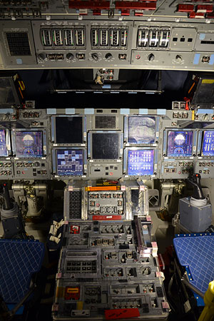
Space Shuttle Cockpit, Photo Courtesy NASA
5. The Reaction Control System, which is made up of thrusters fired to help the Orbiter achieve a precise orbital path or perform changes in its position, and all of their related hardware. Thrusters are located at the forward end of the Orbiter and in each of the two aft Orbital Maneuvering System (OMS)/Reaction Control System (RCS) pods.
The RCS contains a total of 38 primary thrusters and 6 vernier thrusters. The forward RCS array contains 14 primary thrusters and two vernier thrusters. A total of 12 primary thrusters and two vernier thrusters are housed in each of the two OMS/RCS pods.
Each RCS thruster burns a combination of monomethyl hydrazine and nitrogen tetroxide liquid fuel. Each primary thruster can produce a thrust of 870 pounds, while each vernier thruster can produce a thrust of 24 pounds. The RCS thrusters can be fired in a plethora of combinations depending on the specific mission requirements.
6. The Electrical Power System, which provides the Orbiter with electricity. The Electrical Power System is made up of the Power Reactant Storage and Distribution Subsystem, the Fuel Cell Power Plants and the Electrical Power Distribution and Control Subsystem.
The Power Reactant Storage and Distribution Subsystem stores and delivers liquid oxygen and liquid hydrogen fuel to three Fuel Cell Power Plants. In burning the liquid oxygen and liquid hydrogen, the Fuel Cell Power Plants are each capable of producing 21,000 watts of continuous output, plus 15-minute peaks of up to 36,000 watts.
Electrical power produced by the Fuel Cell Power Plants is distributed and regulated by the Electrical Power Distribution and Control Subsystem. Prior to launch, Orbiter electricity is provided by ground systems and the Fuel Cell Power Plants. The Fuel Cell Power Plants assume full control of Orbiter power at launch minus 3.5 minutes.
7. The Environmental Control and Life Support System, which controls and regulates the astronaut life support functions of the Orbiter. Life support functions include crew compartment pressure, cabin air revitalization, water cooling, temperature control, water supply, waste collection, airlock support and crew altitude protection.
8. The Auxiliary Power Unit System, which is a storable liquid hydrazine-fueled, turbine-driven power unit that generates mechanical shaft power to drive a hydraulic pump that produces hydraulic pressure for the Orbiter hydraulic system.
The Auxiliary Power Unit System is vital to the Orbiter, since it controls hydraulic devices that gimbal the Space Shuttle Main Engines, operate various propellant valves in the Space Shuttle Main Engines and move the Orbiter elevons, body flap and rudder speed brake.
In addition, the Auxiliary Power Unit System controls devices that retract the External Tank/Orbiter 17-inch disconnects, deploy and retract the landing gear and support the braking and steering of the Orbiter at landing.
The Auxiliary Power Unit System is made up of three Auxiliary Power Units (APU) located in the aft fuselage. Each APU is identical, but each is operated independently of the others. All three APU’s are started five minutes before launch, and are turned off shortly before the Orbiter reaches orbit.
One APU is started shortly before the Orbiter makes its de-orbit burn, with the remaining two APU’s started just after the de-orbit burn is completed. All three APU’s run until the Orbiter completes its landing and rollout.
9. The Water Spray Boiler System, which cools the Auxiliary Power Unit (APU) lubrication oil and hydraulic fluid. Three independent Water Spray Boilers each serve a corresponding APU. The Water Spray Boiler System sprays water onto the APU lubrication oil and hydraulic fluid lines, thus cooling the fluids within them.
10. The Hydraulic System, which distributes the hydraulic pressure produced by the Auxiliary Power Unit (APU) System. The Hydraulic System is made up of three independent hydraulic systems, each of which is mated to a corresponding APU.
11. The Landing Gear System, which is a conventional aircraft tricycle configuration landing gear consisting of a single forward nose landing gear and a left and right main landing gear. Each landing gear includes a shock strut with two tire and wheel assemblies.
Each main landing gear wheel is equipped with a brake assembly with anti-skid protection. The nose landing gear is steerable. The landing gear are retracted and deployed by hydraulic mechanism, and are locked in position within a wheel well and protected by landing gear doors when not in use.
12. The Caution and Warning System, which is designed to warn the crew of any conditions that may adversely affect the performance of the Orbiter. The Caution and Warning System primarily consists of a set of visual and aural alarms that alert the crew when any system has exceeded or strayed from its operational limits.
13. The Orbiter Lighting System, which provides both interior and exterior lighting for the Orbiter. Interior lighting is used primarily to support crew operations. Exterior lighting is used primarily to illuminate the payload bay area in order to aid visibility during payload operations and spacewalks.
14. The Smoke Detection and Fire Suppression System, which is designed to warn the crew of any fires, as well as protect the Orbiter from any fires that might develop. The system is made up of smoke detectors, portable fire extinguishers and automatic fire extinguishers.
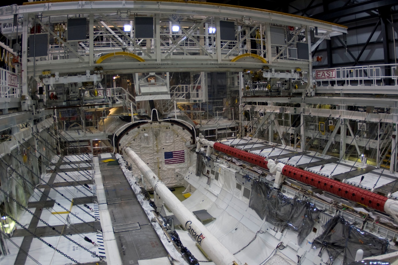
Space Shuttle Cargo Bay, Photo Courtesy NASA
15. The Payload Deployment and Retrieval System, which includes an electromechanical arm that maneuvers a payload from the payload bay and back again, plus all of its related hardware. This is more commonly known as the Remote Manipulator System (RMS), and is operated by the crew from inside the Orbiter.
The RMS can remove payloads from the payload bay for deployment. It can also grapple free-flying payloads and berth them back in the payload bay. It has been used to grapple satellites and the Hubble Space Telescope for repair and redeployment.
The RMS has also acted as an aid to astronauts participating in spacewalks. It has been used as a mobile extension ladder, work station and foot restraint for astronauts working in the payload bay during spacewalks. Cameras attached to the RMS have also been used to aid astronauts in visual inspections of the payload bay area.
16. The Payload Retention System, which is made up of a wide variety of hardware used to keep payloads secure within the payload bay. The Payload Retention System is designed to provide three-axis support for up to five separate payloads per mission.
17. The Communications System, which consists of all the equipment necessary to support the flow of voice and data transmissions to and from the Orbiter. Primary communications to and from the Orbiter flow through the NASA Space Flight Tracking and Data Network and the Tracking and Data Relay Satellite System.
The Communications System incorporates a huge and complex network of communications equipment and instrumentation. In addition to allowing both visual and aural communication with the crew, the Communications System supports a constant flow of data regarding the performance of the Orbiter, its systems and its position.
18. The Avionics System, which controls or assists in the control of most Orbiter systems. Primary functions of the Avionics System include automatic determination of Space Shuttle operational readiness, plus sequencing and control of the Solid Rocket Boosters and External Tank during launch and ascent.
The Avionics System also monitors the performance of the Orbiter, supports digital data processing, communications and tracking, payload and system management, guidance, navigation and control, as well as the electrical power distribution for the Orbiter, External Tank and Solid Rocket Boosters.
The Avionics System is made up of more than 300 computer black boxes located at various positions in the Orbiter, connected by about 300 miles of electrical wiring. A number of redundant hardware and software back-ups are incorporated within the Avionics System due to its critical nature.
Remarkably, the Avionics System is so complex that it can support fully automatic flight of the Space Shuttle from launch through landing. Although the Space Shuttle is typically guided to the runway manually during landing, the Avionics System can perform all flight functions automatically, with the exception of on-orbit rendezvous.
19. The Purge, Vent and Drain System, which is designed to produce gas purges that help regulate Orbiter temperature, prevent the accumulation of hazardous gases, vent unpressurized compartments during ascent and re-entry, drain any excess trapped fluids and keep window cavities clear.
The Purge, Vent and Drain System is made up of three separate sets of distribution plumbing located throughout the Orbiter. Purge gas consists of cool, dry air and gaseous nitrogen. Using a number of purge ports and vents, the system maintains constant humidity and temperature and assures that contaminants cannot enter the Orbiter.
20. The Orbiter Flight Crew Escape System, which is a system designed to allow the crew to escape the Orbiter under a variety of flight situations. The system consists of an Inflight Crew Escape System, Emergency Egress Slide and Secondary Emergency Egress hardware.
The Inflight Crew Escape System, introduced after the Challenger accident, allows the crew to bail out of the Orbiter during flight. It will not, however, allow the crew to escape under circumstances similar to the Challenger accident. To use this system, the Orbiter must be on a level glide path.
The specific scenario under which astronauts might benefit from the Inflight Crew Escape System would be if the Orbiter could for some reason not reach a runway. Since astronauts might not survive either a water or land ditching of the Orbiter, the Inflight Crew Escape System does provide significant advantages.
Using the Inflight Crew Escape System, the astronauts would first blow the side hatch door. They would then deploy an escape pole, which extends from the inside to the outside of the Orbiter. The astronauts would then each use hardware attached to their space suits to slide along the escape pole, then parachute to safety.
Should the astronauts need to escape the Orbiter after performing a landing, an Emergency Egress Slide can be deployed out the side hatch after the hatch is blown or opened manually. Secondary Emergency Egress is provided by blowing the left overhead window, after which hardware allows astronauts to be safely lowered to the ground.
The Space Shuttle Orbiter has proven itself to be a versatile, reliable vehicle capable of carrying out a number of tasks.
Space Shuttle Underbelly, Photo Courtesy NASA
Employing a payload bay measuring 60 feet long by 15 feet wide, the Orbiter was designed to carry payloads into space and perform missions at orbital altitudes ranging from 115 to 250 miles.
Payload capability averaged about 37,800 pounds per mission, but under certain conditions heavier payloads could be carried. An Orbiter performing a mission at a lower altitude would be able to carry a heavier payload than one performing a mission at a higher altitude.
Given Space Shuttle performance enhancements like lighter weight External Tanks and improved Main Propulsion System, Space Shuttle payload capability peaked at about 60,000 pounds.
The Orbiter was designed to carry a maximum crew of eight astronauts, although it could carry up to ten astronauts in an emergency. The Orbiter carried all of the supplies and equipment necessary for the crew to perform its mission.
The mission duration of the Orbiter was typically seven to nine days, although certain Orbiters were modified to allow missions of up to 16 days. The Orbiter afforded its occupants a shirt-sleeve environment, and never produced stresses in excess of three g’s, which is less than many amusement park thrill rides.
The Orbiter was launched in an upright position, with thrust provided by three Space Shuttle Main Engines (SSME) and two Solid Rocket Boosters (SRB). SRB separation occurred about two minutes after launch, and the SSME’s burned for about 8.5 minutes after launch.
The SSME’s shut down just before the Orbiter reached orbit. The External Tank (ET) that provided fuel for the SSME separated from the Orbiter shortly after SSME cutoff. Combinations of the 38 reaction control thrusters and six vernier thrusters are fired to stabilize the Orbiter during ET separation and helped clear the Orbiter from the ET.
Combinations of the reaction control thrusters and vernier thrusters are also fired to support attitude pitch, roll and yaw maneuvers as the Orbiter continued its ascent after ET separation. The two orbital maneuvering system engines were then fired to place the Orbiter on its proper orbit.
Once the Orbiter reached its proper orbit, the orbital maneuvering system engines could be fired again to support any major velocity maneuvers that became necessary. Combinations of the reaction control thrusters and vernier thrusters could be fired to support precision operations such as rendezvous and docking operations.
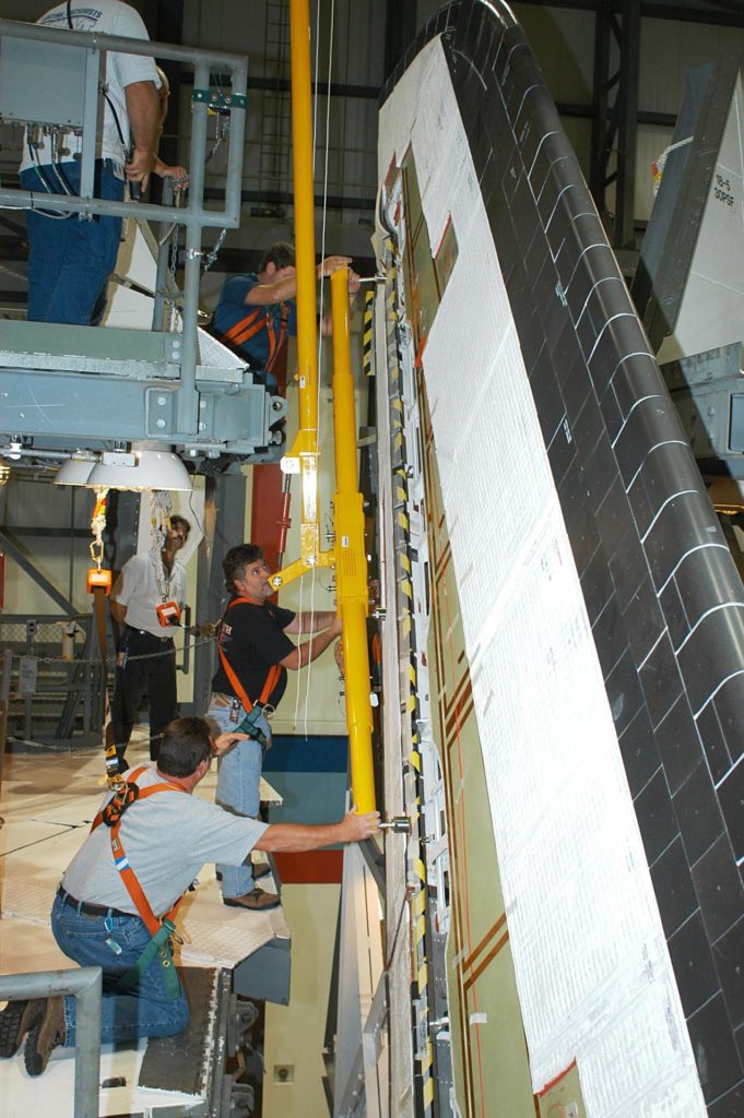
Space Shuttle Tail Fin, Photo Courtesy NASA
Once the mission was completed, the orbital maneuvering system engines were fired to slow the Orbiter in what is called the deorbit burn, or deorbit maneuver. Once in orbit, the Orbiter travelled at a speed of about 25,400 feet per second. The deorbit burn decreased the Orbiter speed to about 300 feet per second as it prepared for re-entry.
The unpowered Orbiter then re-entered the atmosphere, and is guided to a precision landing like a traditional aircraft. There were three Space Shuttle landing sites available in the United States. These were located at the Kennedy Space Center in Florida, Edwards Air Force Base in California and White Sands in New Mexico.
Once on the ground, a number of highly specialized vehicles approached the Orbiter to perform a variety of servicing and safety tasks prior to crew egress. Great care was taken to provide for the safety of the crew and prevent toxic fuels and gases from harming the environment.
The Orbiter was then routinely serviced for its next mission in a turnaround that typically took two to three months. In certain circumstances, the Orbiter was ferry-flown to California for factory modifications or major servicing.
In the event an emergency was encountered during flight, the Orbiter had several flight options available. These included:
1. Return To Launch Site (RTLS), in which the Orbiter could return to the Kennedy Space Center if all thrust was lost from one Space Shuttle Main Engine (SSME) between liftoff and launch plus 4 minutes, 20 seconds, after which time there was not enough fuel available to support this type of abort.
An RTLS abort consisted of a powered stage, at which time the SSME’s were still firing. This would be followed by an External Tank separation stage, which could not occur until after the Solid Rocket Boosters were jettisoned. Finally, the Orbiter could be maneuvered into a glide stage for a return to the launch site.
2. Transatlantic Abort Landing (TAL), in which the Orbiter could land at an overseas abort landing site if a Space Shuttle Main Engine (SSME) failed after the last RTLS abort opportunity but before any other abort could be accomplished. The TAL abort would also be attempted if an Orbiter system failure prevented any other type of abort.
Using the TAL abort, the Orbiter could complete a powered flight on a ballistic path across the Atlantic Ocean, and would then perform a glide landing at a pre-selected runway located in either the city of Moron in Spain, the city of Dakar in Senegal or the city of Ben Guerur in Morocco.
3. Abort To Orbit (ATO), in which the Orbiter could reach a lower, but safe, orbit if a propulsion failure did not allow it to reach its intended orbit. An ATO was performed during Space Shuttle Mission STS-51F, in which Challenger was able to successfully complete its mission at a lower orbital altitude.
4. Abort Once Around (AOA), in which the Orbiter could travel once around the Earth before making a landing in the United States. The AOA would be used if a propulsion failure did not allow the Orbiter to maintain any orbit, even one lower than intended.
The AOA would also be used if for some reason a system failure required the Orbiter to land quickly after it reached orbit. For all intents and purposes, an AOA would be performed in a similar manner to a normal re-entry and landing.
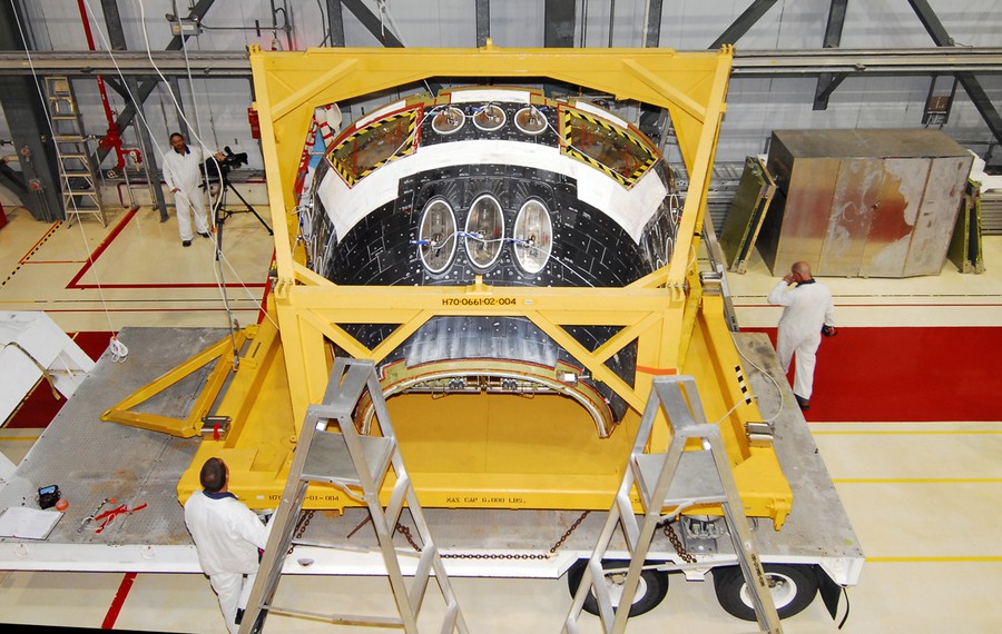
Space Shuttle Nose Assembly, Photo Courtesy NASA
5. Contingency Abort, which would be used if the Orbiter could not land on a runway. During a Contingency Abort, the Orbiter would ideally be guided to a safe glide path to allow the astronauts to use the Inflight Crew Escape System. If a safe glide path was not possible, the Orbiter would have to be ditched with the crew aboard.
The Space Shuttle Orbiter has proven itself to be a versatile vehicle, and has supported a number of diverse mission applications. These have included the deployment of a variety of scientific, military and commercial satellites and the deployment of scientific space probes.
A vast number of scientific investigations have been conducted aboard Space Shuttle Orbiters, including those performed inside pressurized laboratory modules housed in the Orbiter payload bay. Many scientific payloads have been carried in the Orbiter payload bay, including free-flying satellites that were deployed and retrieved.
Many scientific accomplishments have been made through spacewalks conducted from the Orbiter. In addition to rehearsing construction techniques for the International Space Station, astronauts have demonstrated that on-orbit repair and maintenance of satellites is possible, as are a number of on-orbit troubleshooting activities.
Space Shuttle Orbiters also have completed an ambitious docking program with the Russian Mir Space Station and the International Space Station, helping to extend an unprecedented continuous U.S. presence in space while ushering in a new era of international cooperation in space.
SPACE SHUTTLE MAIN ENGINES
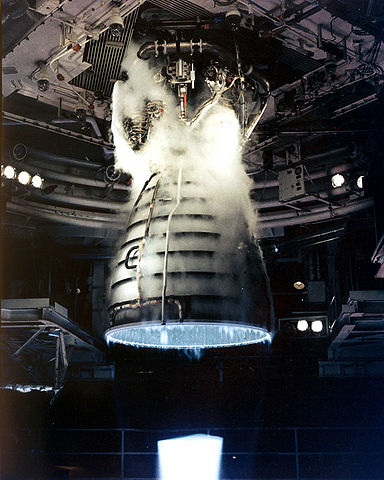
Length: 14 feet
Diameter: 7 feet, 6 inches
Space Shuttle Main Engines (SSME) were the most advanced liquid-fueled rocket engines ever built. They were manufactured by the Rocketdyne Division of Rockwell, located at Canoga Park, California. Each Space Shuttle Orbiter had three SSME’s mounted on the aft fuselage in a triangular pattern. Each SSME was designed for 7.5 hours of operation over an average lifespan of 55 starts. SSME’s burned a combination of liquid oxygen and liquid hydrogen fed from the Space Shuttle External Tank (ET). The SSME’s employed a staged combustion cycle, in which the fuels were first partially burned at high pressure and low temperature, then burned completely at high pressure and high temperature. The staged burning of fuel allowed the SSME’s to produce thrust more efficiently than other rocket engines. A rapid burning of fuel in a staged burn gave SSME’s a combustion efficiency of about 99%.
SSME thrust was variable, which was extremely important in Space Shuttle mission applications. SSME thrust could be varied from a range of 65% minimum to 109% maximum of their 100% rated power levels at precise increments of 1% as needed. A thrust value of 100%, called rated power, corresponded to a thrust of 375,000 pounds per each SSME at sea level, or 470,000 pounds of thrust per each SSME in a vacuum. A thrust value of 104%, called full power, which was typically employed as the Space Shuttle ascended, corresponded to a thrust of 393,800 pounds per each SSME at sea level, or 488,800 pounds of thrust per each SSME in a vacuum. In an emergency, each SSME could be throttled up to 109% power. This corresponded to a thrust of 417,300 pounds of thrust per each SSME at sea level, or 513,250 pounds of thrust per each SSME in a vacuum.
All three SSME’s received identical throttle commands at the same time. Throttle commands usually came from general purpose computers aboard the Orbiter. In an emergency, however, throttle commands could be controlled manually from the flight deck. Firing of the three SSME’s began at Launch Minus 6.6 seconds, at which time general purpose computers aboard the Orbiter commanded a staggered start of each SSME. The first to fire was Main Engine Number Three (right), followed by Main Engine Number Two (left) and Main Engine Number One (center) at intervals of 120 milliseconds. If all three SSME’s did not reach a mandatory thrust of 90% over the course of the next three seconds, a Main Engine Cutoff command was initiated automatically, followed by the cutoff of all three SSME’s and a number of safety functions.
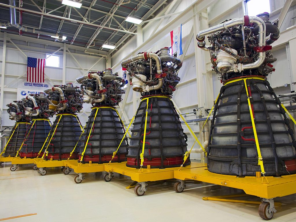
Space Shuttle Main Engines, Photo Courtesy NASA
If all three SSME’s were performing normally, the Space Shuttle could be launched. The SSME’s achieved full power at launch, but were throttled back at about Launch Plus 26 seconds in order to protect the Space Shuttle from aerodynamic stress and excessive heating. The SSME’s were throttled back up to full power at about Launch Plus 60 seconds, and typically continued to produce full power until shortly before the Space Shuttle reached orbit. During ascent, each SSME could be gimbaled plus or minus 10.5 degrees pitch and yaw to help steer the Space Shuttle. The SSME’s typically burned for about 8.5 minutes after launch. At about Launch Plus 7 minutes, 40 seconds the SSME’s were throttled down so that the Space Shuttle would not experience gravitational force in excess of three g’s. Gravitational forces in excess of three g’s might adversely affect the Space Shuttle and its crew. At about ten seconds before Main Engine Cutoff (MECO), a MECO sequence began. About three seconds later, the SSME’s were commanded to begin throttling back at intervals of 10% thrust per second until they reached a thrust of 65% of rated power, called minimum power. Minimum power was maintained for just under seven seconds, then the SSME’s shut down.
The SSME’s were controlled during flight by digital computer systems mounted on each engine. These operated in conjunction with engine sensors, valve actuators and spark igniters to provide a redundant, self-contained system for monitoring engine control, checkout and status. The SSME digital computer systems, called Main Engine Controllers, were mounted on the top of each SSME, on the outside of the combustion chamber. Each SSME had one Main Engine Controller, which consisted of two digital computers and their related electronics. In association with general purpose computers aboard the Orbiter, the SSME Main Engine Controllers were able to provide flight readiness verification, engine start and shutdown sequencing, closed-loop thrust and propellant mixture ratio control and sensor operation.
The Main Engine Controllers also produced valve actuator and spark igniter control signals, performed engine performance monitoring and limiting functions, responded to Orbiter commands plus transmitted and stored engine status, performance and maintenance data. Following MECO, the SSME’s had completed their function and were no longer needed during a Space Shuttle mission. SSME’s were thoroughly inspected, checked and tested after each Space Shuttle flight. Each SSME could be replaced or changed out as necessary. On rare occasions, SSME’s were static tested on the launch pad in what is called a Flight Readiness Firing (FRF). An FRF was typically performed when engines that had never been flown were to be used for the first time during a Space Shuttle mission. In a typical FRF, all three SSME’s were simultaneously fired for about ten seconds.
SPACE SHUTTLE EXTERNAL TANK
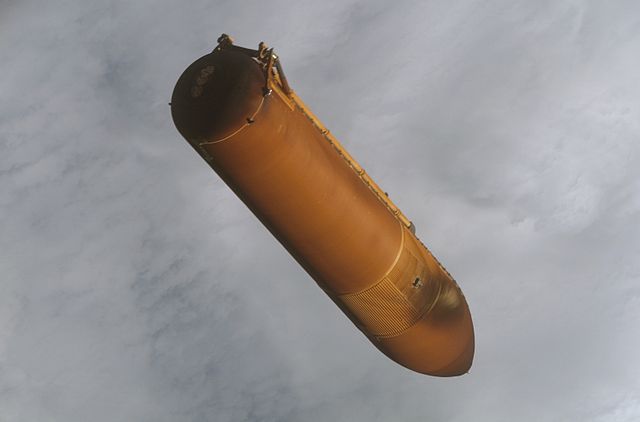
Space Shuttle External Tank, Photo Courtesy NASA
Length: 153 feet, 10 inches
Diameter: 27 feet, 7 inches
The External Tank (ET) was the only non-reusable element of the Space Shuttle. It was also the largest element of the Space Shuttle, and provided the structural backbone of the entire system. The chief purpose of the ET was to carry the liquid fuels necessary to provide power for the Orbiter’s three main engines. Martin Marietta (later Lockheed Martin) won a competitive contract to design and manufacture the Space Shuttle ET in 1973. The contract specified that the ET be constructed at the NASA Michoud Assembly Facility in New Orleans, Louisiana. The Michoud plant afforded ample space to support construction of ET’s, plus deep-water port access to allow transportation of ET’s by enclosed barge to the Kennedy Space Center. Completed ET’s were individually barged to the Kennedy Space Center in a voyage that typically took 4 to 5 days.
For many years, the ET barge was towed to and from the Kennedy Space Center by leased tug. In 1998, however, NASA opted to save money by introducing a policy of towing the ET barge to and from the Kennedy Space Center by one of the Solid Rocket Booster (SRB) retrieval ships, whose crews would otherwise have remained idle. The first ET was delivered to NASA on September 7, 1977. This was not a flight-ready ET, but rather was used for tests in association with the Space Shuttle Main Propulsion Test Article (MPTA-098) assembled at the Rockwell plant at Palmdale, California. Three test ET’s were ultimately delivered to NASA. The first flight-ready ET was delivered to NASA on June 29, 1979. The first six ET’s delivered to NASA were called the Standard Weight Tank (SWT), with each tank weighing 75,500 pounds. SWT’s were flown on Space Shuttle Missions STS-1 through STS-5 and STS-7.
During Space Shuttle Missions STS-1 and STS-2, the ET’s were painted white. NASA quickly determined that hundreds of pounds of weight and thousands of dollars in preparation work would be saved if the ET’s remained unpainted, and so all ET’s flown from STS-3 onward remained unpainted, sporting an orange-brown color. In 1979, even before a Space Shuttle had completed a space flight, NASA issued a directive that ET’s be lightened by at least 6,000 pounds so that Space Shuttles would be able to carry proportionally heavier payloads. The resulting ET was called the Lightweight Tank (LWT) which was made 10,000 pounds lighter than the SWT through several methods, including materials and design changes and the use of new fabrication techniques. The 65,500-pound LWT was first flown on Space Shuttle Mission STS-6, and then from STS-8 through STS-90.
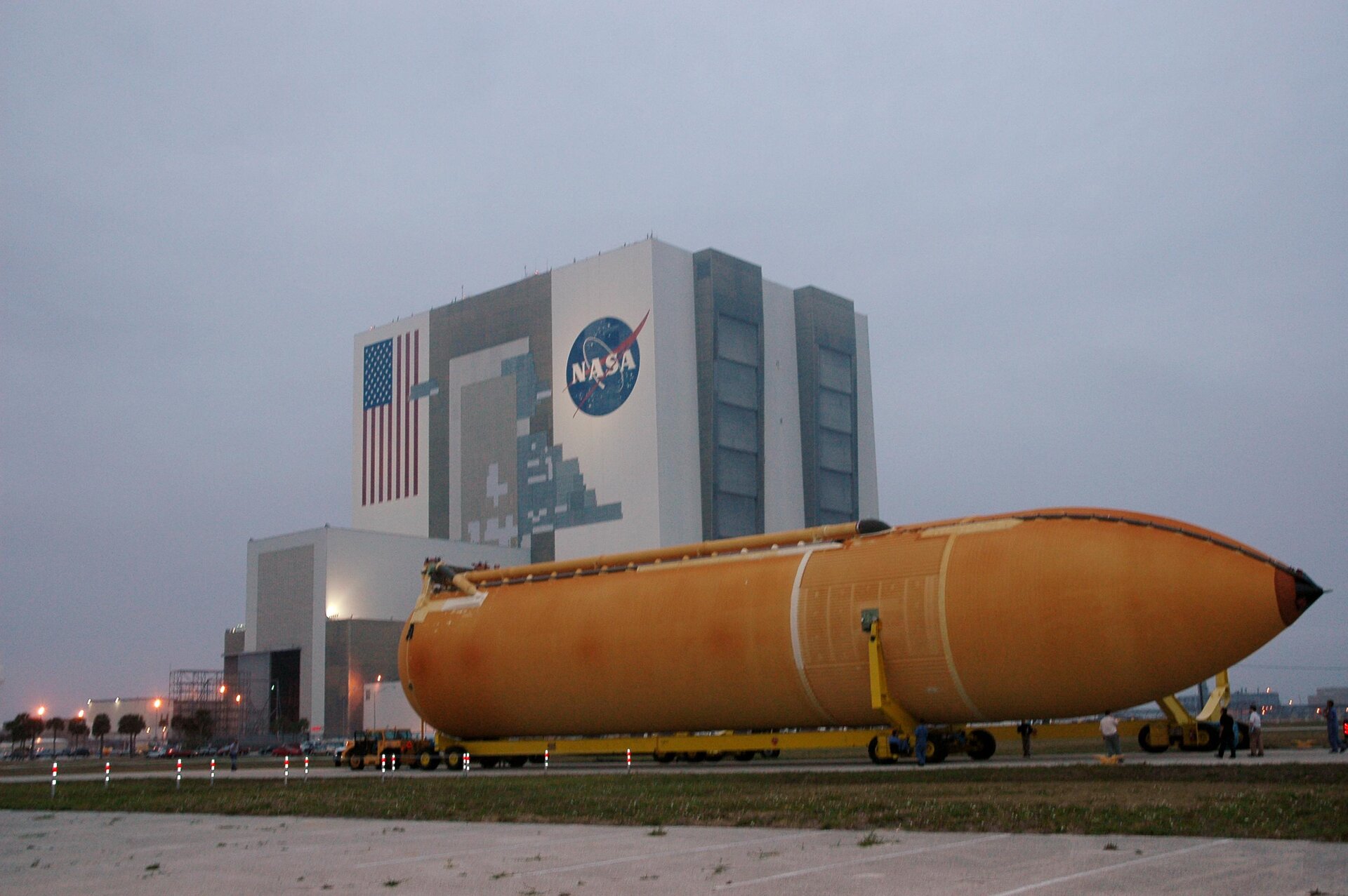
Space Shuttle External Tank, Photo Courtesy NASA
Beginning with Space Shuttle Mission STS-91, a new ET called the Super Lightweight Tank (SLWT) were flown. At a weight of 58,000 pounds, the SLWT is 7,500 pounds lighter than the LWT. The SLWT was introduced primarily to allow NASA to carry heavier payloads aboard the Space Shuttle in support of International Space Station construction. Weight savings in the SLWT were created primarily by constructing the ET from an aluminum-lithium alloy. Previous versions of the ET were constructed using an aluminum-steel alloy and titanium. In general terms, however, much about all three versions of the ET were identical. Each ET was comprised of a liquid oxygen tank located at the top and a liquid hydrogen tank located at the bottom. The liquid oxygen tank was connected to the liquid hydrogen tank by an intertank, which was located in between the other two. The intertank was designed to receive and distribute all thrust loads that the SRB’s produce during launch and flight. The intertank was able to absorb and transfer these loads evenly, providing vital structural integrity for the Space Shuttle. The intertank was 22 feet, 6 inches long by 27 feet, 7 inches wide.
The liquid oxygen tank was 54 feet, 7 inches long by 27 feet, 7 inches wide and carried 145,138 gallons of liquid oxygen weighing 1,380,000 pounds. The liquid hydrogen tank was 96 feet, 8 inches long by 27 feet, 7 inches wide and carried 390,139 gallons of liquid hydrogen weighing 230,000 pounds. Fully loaded with a total of 1,610,000 pounds of liquid fuel, the SLWT version of the ET weighed 1,668,000 pounds at liftoff. Liquid oxygen was stored aboard the ET at a temperature of -297 degrees Fahrenheit, while the liquid hydrogen was stored aboard the ET at a temperature of -423 degrees Fahrenheit. Since the liquid fuels stored inside the ET were this cold, the outer surface of the ET required thermal protection. This was provided by a one inch layer of spray-on foam insulation applied over the forward portion of the liquid oxygen tank, the intertank and the sides and bottom of the liquid hydrogen tank. This foam insulation was intended to reduce ice or frost formation on the tank, which could both increase the weight of the ET and become hazardous to the Space Shuttle during launch. The foam insulation also served to protect the ET from the effects of engine and aerodynamic heating, which could potentially cause the liquid fuel to boil.
An ablative coating made of material that flakes off as it becomes hot was applied to the ET external bulges and projections to protect them from aerodynamic heating that developed during flight. The ET also contained systems that were necessary to support its operation. These included a pressurization and vent system to regulate the tank pressure, an environmental conditioning system to regulate the temperature and humidity of the intertank area and an electrical system to distribute power and provide lightning protection. Much of this equipment is housed in the intertank. All fluid control mechanisms and valves that regulate performance of the ET, with the exception of the vent control valves, were located in the Orbiter. This was due to the cost savings over replacing this equipment after every Space Shuttle mission, since the ET could not be recovered. The ET supplied liquid oxygen and liquid hydrogen to the Orbiter’s three main engines through 17-inch diameter feed lines. The liquid oxygen was fed at a rate of 159,480 pounds, or 16,800 gallons, per minute while the liquid hydrogen was fed at a rate of 26,640 pounds, or 45,283 gallons, per minute. At launch, the ET was attached to both the Orbiter and SRB’s. The SRB’s were jettisoned from the ET about two minutes after launch. The ET typically emptied about 8.5 minutes after launch, at which time it was detached from the Orbiter, broke up and fell into a predetermined area of either the Pacific or Indian Ocean.
SPACE SHUTTLE SOLID ROCKET BOOSTERS
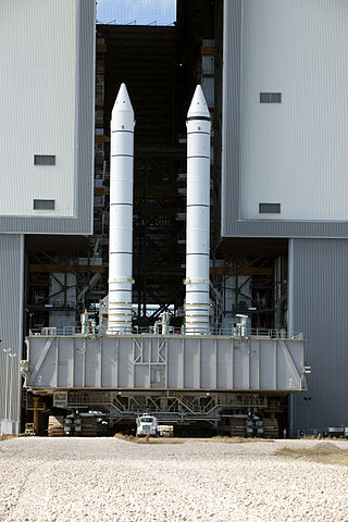
Space Shuttle Solid Rocket Boosters, Photo Courtesy NASA
Length: 149 feet, 2 inches
Diameter: 12 feet, 2 inches
The vast majority of thrust needed to launch the Space Shuttle was provided by two Solid Rocket Boosters (SRB). SRB’s were manufactured by the Wasatch Division of Morton Thiokol Corporation, located in Brigham City, Utah. In addition to providing the bulk of Space Shuttle liftoff thrust, the SRB’s supported the entire weight of the Orbiter and External Tank (ET) prior to launch. The Space Shuttle SRB’s were the largest solid-fueled motors ever built, and the first designed to be reused. Each SRB weighed about 1,300,000 pounds at launch. The solid fuel contained in the SRB weighed about 1,100,000 pounds while the inert weight of each SRB was about 200,000 pounds. The primary elements of each SRB were the motor, structure, separation system, operational flight instrumentation, recovery system, pyrotechnics, deceleration system and range safety destruct system.
Each SRB was attached to the ET at the SRB’s aft frame by two lateral sway braces and a diagonal attachment. The forward end of each SRB was attached to the ET at the forward end of the SRB’s forward skirt. On the launch pad, Each SRB was fastened to the Mobile Launcher Platform (MLP) at the SRB aft skirt by four large bolts and nuts that were severed by small explosive charges at liftoff. The propellant mixture in each SRB was made up of 69.6% ammonium perchlorate oxidizer, 16% aluminum fuel, 0.4% iron oxide catalyst, 12.04% polymer binder and 1.96% epoxy curing agent. The propellant was contained within the SRB beginning with an 11-point star-shaped perforation in the forward segment to a double-truncated cone perforation in both of the aft segments and the aft closure segment.
These varying shapes allowed the SRB thrust to be reduced by about 33% at launch plus 50 seconds. This reduction in thrust was intended to alleviate stress to the Space Shuttle as it entered its area of maximum dynamic pressure during ascent. The SRB’s employed during each Space Shuttle mission were matched pairs, each made up of four solid rocket motor segments. To minimize any thrust imbalance, the SRB pairs were matched by loading each of the four SRB segments in pairs using the same batches of solid fuel. The segmented solid rocket motor design assured maximum flexibility during manufacturing operations, and also ease of transportation. The SRB’s were transported to the launch site using heavy-duty rail cars equipped with special SRB covers. The cone-shaped aft skirt of each SRB provided one of the most vital supports for the Space Shuttle prior to launch, since it could react to loads that might shift between the SRB’s and the MLP during pre-launch operations.
Four SRB separation motors were also mounted on the aft skirt of each SRB. The aft section of each SRB contained avionics and a thrust vector control system that consisted of two auxiliary power units, hydraulic pumps, hydraulics systems and a nozzle extension jettison system. The forward section of each SRB contained avionics, a sequencer, four forward separation motors, a nose cone separation system, drogue and main parachutes, recovery beacon, recovery light, range safety system and, in certain flights, a parachute camera system. Each SRB had two integrated electronic assemblies, one at the forward and one at the aft. These assemblies provided the electronic command connections to initiate and control various functions of SRB components during flight. The SRB’s were ignited by electronic command from the Orbiter at Launch Minus Zero, provided that the Space Shuttle Main Engines (SSME) had built up enough thrust to support a launch.
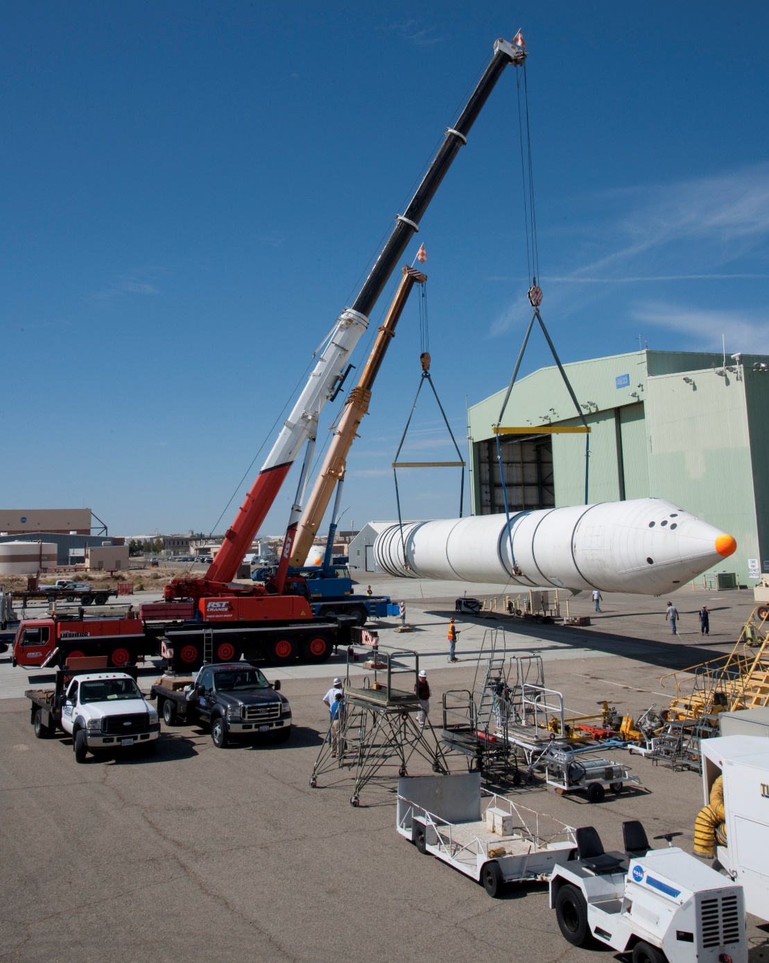
Space Shuttle Solid Rocket Booster, Photo Courtesy NASA
The SSME’s were ignited first, since the SRB’s could not be shut down once they were ignited. The results would be catastrophic if the SRB’s were ignited after an SSME failure on the launch pad. Also at Launch Minus Zero, the four bolts which held each SRB to the MLP were blown by explosive charges. Each bolt measured 28 inches long by 3.5 inches in diameter. Each SRB could produce a thrust of about 3,300,000 pounds of thrust at liftoff. The combined thrust of the SRB’s accounted for just over 70% of the total thrust needed to carry the Space Shuttle into space. Each SRB exhaust nozzle could be gimbaled up to eight degrees to help steer the Space Shuttle during ascent. About 125 seconds after launch and at an altitude of about 150,000 feet, the SRB’s burned out and were jettisoned from the ET. The jettison command originated from the Orbiter, and jettison occurred when the forward and aft attach points between the SRB’s and ET were blown by explosive charges.
Milliseconds after SRB separation, 16 solid-fueled separation motors, four in the forward section of each SRB and four in the aft skirt of each SRB, were fired for just over one second to help carry the SRB’s away from the rest of the Space Shuttle. Each of the separation motors could produce a thrust of about 22,000 pounds. The SRB’s continued to ascend in a slow, tumbling motion for about 75 seconds after SRB separation, to a maximum altitude of about 220,000 feet. The SRB’s then began to quickly fall toward the Atlantic Ocean. About 225 seconds after SRB separation and at an altitude of about 15,700 feet the nose cap of each SRB was ejected, which resulted in deployment of a pilot parachute. The pilot parachute had a diameter of 11.5 feet, and provided the force necessary to activate mechanisms which pulled the drogue parachute from its stored position.
The drogue parachute had a diameter of 54 feet, and was used to orient and stabilize the descent of each SRB to a tail-first attitude in preparation for the deployment of the main parachutes. About 248 seconds after SRB separation and at an altitude of about 6,000 feet, deployment of the main parachutes began. Three main parachutes were deployed on each SRB. Each main parachute had a diameter of 136 feet. The main parachutes accompanied each SRB to water impact, which occurred about 295 seconds after SRB separation at a speed of about 81 feet per second. The SRB’s impacted the Atlantic Ocean about 140 miles from the launch site. Since each SRB impacted the water nozzle-first, air trapped within the SRB casings caused each SRB to float with its forward end extended about 30 feet out of the water.
Crews aboard specialized SRB retrieval ships quickly set about locating each SRB by homing in on radio beacon signals transmitted from each SRB. Crews could also be aided in locating the SRB’s by flashing lights activated on each SRB. Once located, the crews began recovering each SRB, plus the drogue parachutes and main parachutes. The SRB nozzles were then plugged, the solid rocket motors dewatered and the SRB’s towed back horizontally to a receiving and processing site on Cape Canaveral Air Force Station. There, each SRB was removed from the water. After a set of thorough inspections, the SRB components were disassembled and washed with fresh and deionized water to limit saltwater corrosion. Refurbishing of each SRB then began, with some components sent back to the manufacturer and some components remaining at the launch site.
SPACE SHUTTLE COLUMBIA (OV-102)
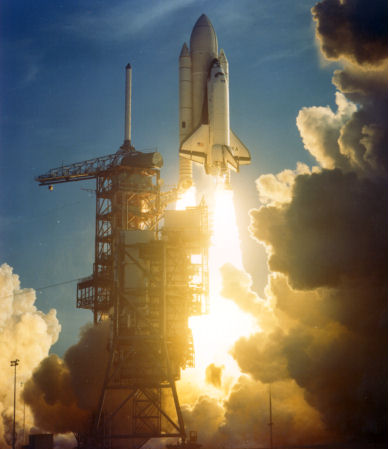
Space Shuttle Columbia, Photo Courtesy NASA
Date of First Launch: April 12, 1981
Date of Final Launch: January 16, 2003
Number of Launches: 28
Columbia was named after the Boston-based sloop of the late 1700’s, captained by Robert Gray. Other vessels named Columbia included the first U.S. Navy ship to circle the globe and the Command Module flown during Apollo 11, the first mission to land men on the Moon. Columbia was the first Space Shuttle ever launched when it began its maiden flight of STS-1 on April 12, 1981. Columbia was the first Orbiter to undergo the scheduled inspection and retrofit program. It was transported to Rockwell International’s Palmdale, California assembly plant on August 10, 1991 following the completion of mission STS-40. The Orbiter underwent about 50 modifications including the addition of carbon brakes, drag chute, improved nose wheel steering, removal of obsolete flight instrumentation and enhancements to its thermal protection system.
Columbia returned to the Kennedy Space Center on February 9, 1992 for processing for mission STS-50. On October 8, 1994 Columbia was again transported to Palmdale for about 90 additional enhancements, including upgrades to the main landing gear thermal barrier, tire pressure monitoring and radiator drive circuitry. On September 24, 1999 Columbia made its last trip to Palmdale for about an additional 100 modifications, including the addition of a glass cockpit display. Columbia’s missions included STS-1, STS-2, STS-3, STS-4, STS-5, STS-9, STS-61C, STS-28, STS-32, STS-35, STS-40, STS-50, STS-52, STS-55, STS-58, STS-62, STS-65, STS-73, STS-75, STS-78, STS-80, STS-83, STS-94, STS-87, STS-90, STS-93, STS-109 and STS-107. Columbia was destroyed during re-entry on February 1, 2003 at the conclusion of STS-107. Loss of the vehicle and crew were blamed on External Tank insulation which broke off during launch and struck Columbia’s underbelly, damaging its thermal protection and causing the Orbiter to burn up and disintegrate over East Texas.
SPACE SHUTTLE CHALLENGER (STA-099/OV-099)
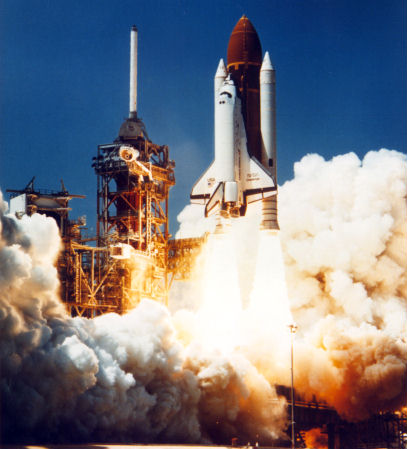
Space Shuttle Challenger, Photo Courtesy NASA
Date of First Launch: April 4, 1983
Date of Final Launch: January 28, 1986
Number of Launches: 10
Challenger was named after the British naval vessel HMS Challenger that sailed the Atlantic and Pacific Oceans in the 1870’s. Challenger was also the name of the Apollo 17 Lunar Module. Space Shuttle Challenger was destroyed 73 seconds after liftoff of mission STS-51L on January 28, 1986. A crew of seven perished. The cause of the accident was determined to be burn through of the right-hand Solid Rocket Booster which resulted in the explosion of the External Tank. Challenger began its career as a high-fidelity structural test article. As such, the Orbiter structure had evolved under such weight-saving pressure that virtually all components of the airframe were required to handle significant structural stress. The Orbiter was subjected to intensive vibration testing over an 11-month period beginning on February 4, 1978.
On January 29, 1979, NASA awarded Rockwell a contract to convert the structural test article into an operational Space Shuttle to alleviate concerns that Columbia would be the only operational Orbiter on hand when the ambitious flight series began. Challenger, along with Discovery, were modified to be able to carry a Centaur upper stage into space as a booster for a number of proposed satellite payloads. These modifications included the addition of increased plumbing to load and vent the Centaur’s liquid oxygen/liquid hydrogen fuel in the Shuttle’s payload bay as well as new controls on the aft flight deck to monitor the Centaur during flight operations. However, the Centaur upper stage was never actually flown as it was considered to be too risky in lieu of the Challenger tragedy. Challenger’s missions included STS-6, STS-7, STS-8, STS-41B, STS-41C, STS-41G, STS-51B, STS-51F, STS-61A and STS-51L, its final and tragic flight.
SPACE SHUTTLE DISCOVERY (OV-103)
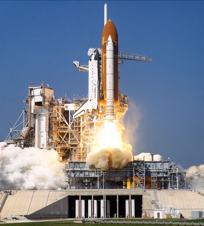
Space Shuttle Discovery, Photo Courtesy NASA
Date of First Launch: August 30, 1984
Date of Final Launch: February 24, 2011
Number of Launches: 39
Discovery was named after one of two ships used by British explorer James Cook in the 1770’s as he explored the South Pacific Ocean. Other ships also carried the name Discovery. These included a ship used by Henry Hudson as he sought a Northwest Passage between the Atlantic and Pacific Oceans in the early 1600’s. Another was a ship used by the British Royal Geographic Society on an expedition to the North Pole in 1875. The organization had a follow-up ship also named Discovery in support of an Antarctic expedition in 1904. Discovery, like Challenger, was modified to be able to carry the Centaur upper stage into space. Discovery also underwent a nine-month Orbiter Maintenance Down Period (OMDP) at the Rockwell plant in Palmdale, California following mission STS-82. This renovation included the addition of an extra cryogenic fuel tank and an external airlock to be employed during trips to the International Space Station. Discovery also underwent another OMDP following mission STS-105. This lasted over two years featuring 99 upgrades and 88 special tests. Discovery’s missions included STS-41D, STS-51A, STS-51C, STS-51D, STS-51G, STS-51I, STS-26, STS-29, STS-33, STS-31, STS-41, STS-39, STS-48, STS-42, STS-53, STS-56, STS-51, STS-60, STS-64, STS-63, STS-70, STS-82, STS-85, STS-91, STS-95, STS-96, STS-103, STS-92, STS-102, STS-105, STS-114, STS-121, STS-116, STS-120, STS-124, STS-119, STS-128, STS-131 and STS-133. Following its retirement in 2011, Space Shuttle Discovery was transported to the Smithsonian Institution in Washington, D.C. Discovery is currently housed in the James S. McDonnell Space Hangar at the National Air and Space Museum’s Steven F. Udvar-Hazy Center in Chantilly, Virginia.
SPACE SHUTTLE ATLANTIS (OV-104)
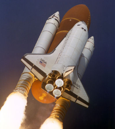
Space Shuttle Atlantis, Photo Courtesy NASA
Date of First Launch: October 3, 1985
Date of Final Launch: July 8, 2011
Number of Launches: 33
Atlantis was named after the primary research vessel of the Woods Hole Oceanographic Institute in Massachusetts from 1930 to 1966. Following mission STS-46, Atlantis was transported to the Rockwell plant in Palmdale, California for an Orbiter Maintenance Down Period (ODMP). A total of 165 modifications were made over a 20-month period and included the installation of a drag chute, new plumbing lines to configure the Orbiter for extended duration missions, more than 800 new heat tiles and blankets, new insulation for the main landing gear and structural modifications to the airframe. Atlantis also underwent a similar ODMP following mission STS-101. About 130 modifications were performed, including the addition of a “glass cockpit”, renovation of the navigation system transitioning it to more modern Global Positioning System (GPS) technology, addition of an airlock and docking mechanisms for missions to the International Space Station and modification to the Orbiter’s thermal insulation to afford a significant weight reduction. Atlantis missions include STS-51J, STS-61B, STS-27, STS-30, STS-34, STS-36, STS-38, STS-37, STS-43, STS-44, STS-45, STS-46, STS-66, STS-71, STS-74, STS-76, STS-79, STS-81, STS-84, STS-86, STS-101, STS-106, STS-98, STS-104, STS-110, STS-112, STS-115, STS-117, STS-122, STS-125, STS-129, STS-132 and STS-135. Following its retirement in 2011, Atlantis was moved to the Kennedy Space Center Visitors Complex. Space Shuttle Atlantis is currently on display in a multi-million dollar facility at the ever-popular complex.
SPACE SHUTTLE ENDEAVOUR (OV-105)
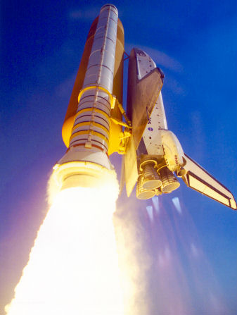
Space Shuttle Endeavour, Photo Courtesy NASA
Date of First Launch: May 7, 1992
Date of Final Launch: May 16, 2011
Number of Launches: 25
Endeavour was named after one of two ships captained by James Cook. Endeavour’s maiden voyage was in 1768 in an exploration of the South Pacific Ocean. For the first time, a Space Shuttle Orbiter’s name was selected via a national competition of elementary and secondary schools. The name Endeavour was announced by President George H.W. Bush in 1989. Endeavour incorporated new hardware designed to improve and expand Orbiter capabilities. Most of this new equipment was installed on the other Orbiters during their scheduled maintenance periods. Specific upgrades introduced on Endeavour included a 40-foot diameter drag chute that reduced landing rollout distance by as much as 2,000 feet, plumbing and electrical connections to allow missions up to 28 days in duration, updated avionics systems, updated navigation including star trackers, improved nosewheel steering as well as an improved version of the Orbiter’s Auxiliary Power Unit which provide power to operate hydraulic systems.
Endeavour underwent its first Orbiter Maintenance Down Period (OMDP) at the Rockwell plant in Palmdale, California following mission STS-77. This OMDP lasted about eight months and included the installation of an external airlock allowing docking to the International Space Station. Endeavour underwent a second OMDP following mission STS-113, this time at the Kennedy Space Center. During this 24-month period, 124 modifications included enhancements to crew safety systems, the addition of a “glass cockpit”, upgrades to the Orbiter’s thermal protection systems and the transition to new and modern Global Positioning System (GPS) guidance. Endeavour’s missions included STS-49, STS-47, STS-54, STS-57, STS-61, STS-59, STS-68, STS-67, STS-69, STS-72, STS-77, STS-89, STS-88, STS-99, STS-97, STS-100, STS-108, STS-111, STS-113, STS-118, STS-123, STS-126, STS-127, STS-130 and STS-134. Following its retirement in 2011, Space Shuttle Endeavour was transported to Los Angeles. After a three-day tow through the streets of Los Angeles, Endeavour found its new home inside the Samuel Oschin Space Shuttle Display Pavillion at the California Science Center. Endeavour is currently on permanent public display at the facility.

